

[Introduction] XCF flotation machine can self-suction slurry, usually with KYF flotation machine to form a unit.
[Capability] 0.2-50 m3/min
[Application] It can be widely used in the separation of non-ferrous metals, ferrous metals and non-metallic minerals, and is suitable for the roughing and sweeping operations of large and medium-sized flotation plants.
[Improvement] The tank body of XCF flotation machine is the same as that of KYF flotation machine. The difference is that there is a cover plate on the top of XCF impeller to form a negative pressure zone, which can self-priming pulp, but the power consumption is slightly higher.
 Chat With Us
 Leave Message
Advantages
Structure

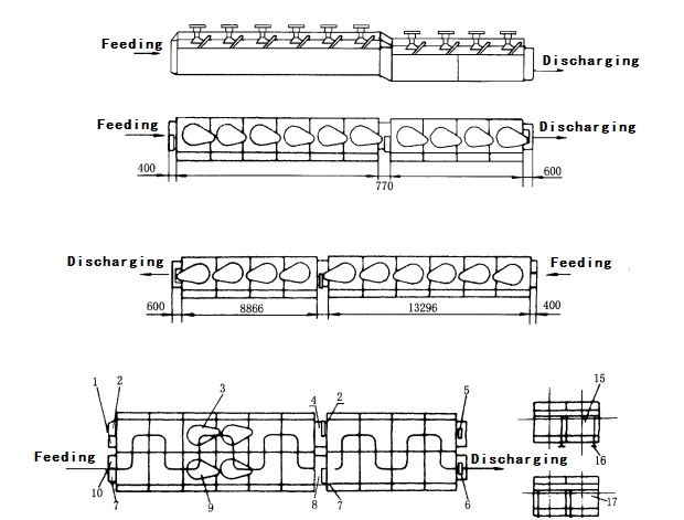
When the XCF flotation machine works, with the impeller rotating, the slurry in the tank is sucked from the bottom of the impeller to the impeller blade. At the same time, the low-pressure air supplied by the blower enters the tank through the air distributor of the hollow shaft and impeller chamber.
After the pulp and air are fully mixed between the blades, the pulp is pushed from the upper part of the impeller to the top of the syncline, and then the steady flow and orientation of the stator enter the whole groove.
The bubble rises to the foam stability zone, and after the enrichment process, the foam flows out of the overflow weir and flows into the foam tank. Another part of the pulp flows to the lower part of the impeller, and then mixes with the impeller to form mineralized bubbles. The remaining pulp flows to the next trough until it finally becomes tailings.
Technical Parameter
|
Model |
Volume m3 |
Capacity m3/min |
Impeller Diameter mm |
Impeller Revolution rpm |
Air Pressure kpa |
Max Air Volume m3/m2·min |
Motor Power kw |
Weight kg |
|
|
Agitation |
Scraping |
||||||||
|
XCF-1 |
1 |
0.2-1 |
400 |
358 |
≥12.6 |
2 |
5.5 |
1.1 |
1154 |
|
XCF-2 |
2 |
0.4-2 |
470 |
331 |
≥14.7 |
7.5 |
1659 |
||
|
XCF-3 |
3 |
0.6-3 |
540 |
266 |
≥19.8 |
11 |
1.5 |
2259 |
|
|
XCF-4 |
4 |
1.2-4 |
620 |
215 |
≥19.8 |
15 |
2669 |
||
|
XCF-8 |
8 |
3.0-8 |
720 |
185 |
≥21.6 |
22 |
3968 |
||
|
XCF-16 |
16 |
4–16 |
860 |
160 |
≥25.5 |
37 |
6520 |
||
|
XCF-20 |
20 |
5-15 |
910 |
155 |
≥25 |
45 |
9200 |
||
|
XCF-24 |
24 |
4-24 |
950 |
153 |
≥30.4 |
55 |
9660 |
||
|
XCF-30 |
30 |
7-15 |
1000 |
141 |
≥31 |
55 |
14810 |
||
|
XCF-38 |
38 |
10-38 |
1050 |
136 |
≥34.3 |
55 |
17000 |
||
|
XCF-40 |
40 |
10-38 |
1050 |
138 |
≥34.3 |
75 |
17500 |
||
|
XCF-50 |
50 |
10-25 |
1120 |
110 |
≥33 |
90 |
22000 |
||
|
XCF-70 |
70 |
13-50 |
1200 |
103 |
≥35 |
90 |
26200 |
||


